Control System for 25L Square Barrel Automatic Filling Machines
For the filling of liquid materials in 25 L square barrels, the position of the mouth of the square barrel is relatively fixed relative to that of the round barrel, which will bring some convenience to the automatic mouth searching during filling. In actual packaging, 25-liter barrels are usually placed on a weighing platform and filled barrel by barrel with a filling gun. Take the filling of 25 L square barrels in an enterprise as an example. Firstly, a wooden pallet is placed on a platform scale, then 12 square barrels in 3 rows and 4 columns are compactly placed on the pallet, and the direction of the barrel mouth is the same. Then, a filling gun is manually used to fill barrels by weight. This kind of filling has the following problems: Each barrel is filled by the operator by observing the value of the weighing instrument, so the accuracy control is difficult to guarantee; The switching of each barrel will cause a small number of materials to leak out of the barrel, resulting in waste and pollution; Workers' labor intensity is high, so they should always keep their attention in a highly concentrated state. If they are slightly negligent, material leakage will occur. The filling machine control system designed in this article effectively solves the above problems, and at the same time greatly improves the filling efficiency, safety and automation level.Structure and principle of filling machines
1. Composition and structure
The structure of the filling machine is mainly composed of a steel structure bracket platform, a scale base, a scale body, a horizontal moving frame, left and right guide rail lifting brackets, lifting linear slide rails, left and right lifting cylinders, a front positioning mechanism, a right positioning mechanism, a stepping motor, a transmission gear and a rack, a material hose, a filling head lifting cylinder, a filling ball valve, a pneumatic control box, a positive pressure control cabinet, etc. The structure diagram of the filling machine is shown in Figure 1. The maximum measuring range of the scale is 1500 kg, and the division value is 0. 5kg; The steel structure platform supports and frames all components of the filling machine; The front and right positioning mechanisms play a positioning role when placing the empty filling barrel to ensure the fixity of the square barrel position; The left and right lifting cylinders can move the entire four-gun-head spray gun assembly up or down, so as to realize the filling of double-layer barrels, and the lifting linear slide rails are installed on both sides of the lifting cylinders; The design of spray gun realized that four barrels of materials can be continuously filled with one-time lifting spray gun, which effectively improves the filling efficiency; The four-bar spray gun and its components are fixed on the horizontal moving frame, and the stepper motor drives the transmission gear rack on the left side of the equipment to realize the accurate positioning function of the spray gun components moving back and forth; Two limit positions of the four spray gun assemblies moving back and forth are respectively provided with limit position detection switches and zero point detection switches; There is a pneumatic control box on the right side and the back side, which is used to install the pneumatic control elements of the filling machine; The filling head lifting cylinder is used for lowering the spray gun into the barrel before filling, and lifting the spray gun out of the barrel after filling; The liquid is conveyed through the material pipeline, and then conveyed to the filling valve of each spray gun through the material hose; 200 L and IBC barrel filling ball valves are used as the backup configuration of this filling machine; PLC, touch screen, weighing instrument and other electrical components are arranged in the positive pressure control cabinet, which is used for explosion-proof occasions and placed next to the filling machine.
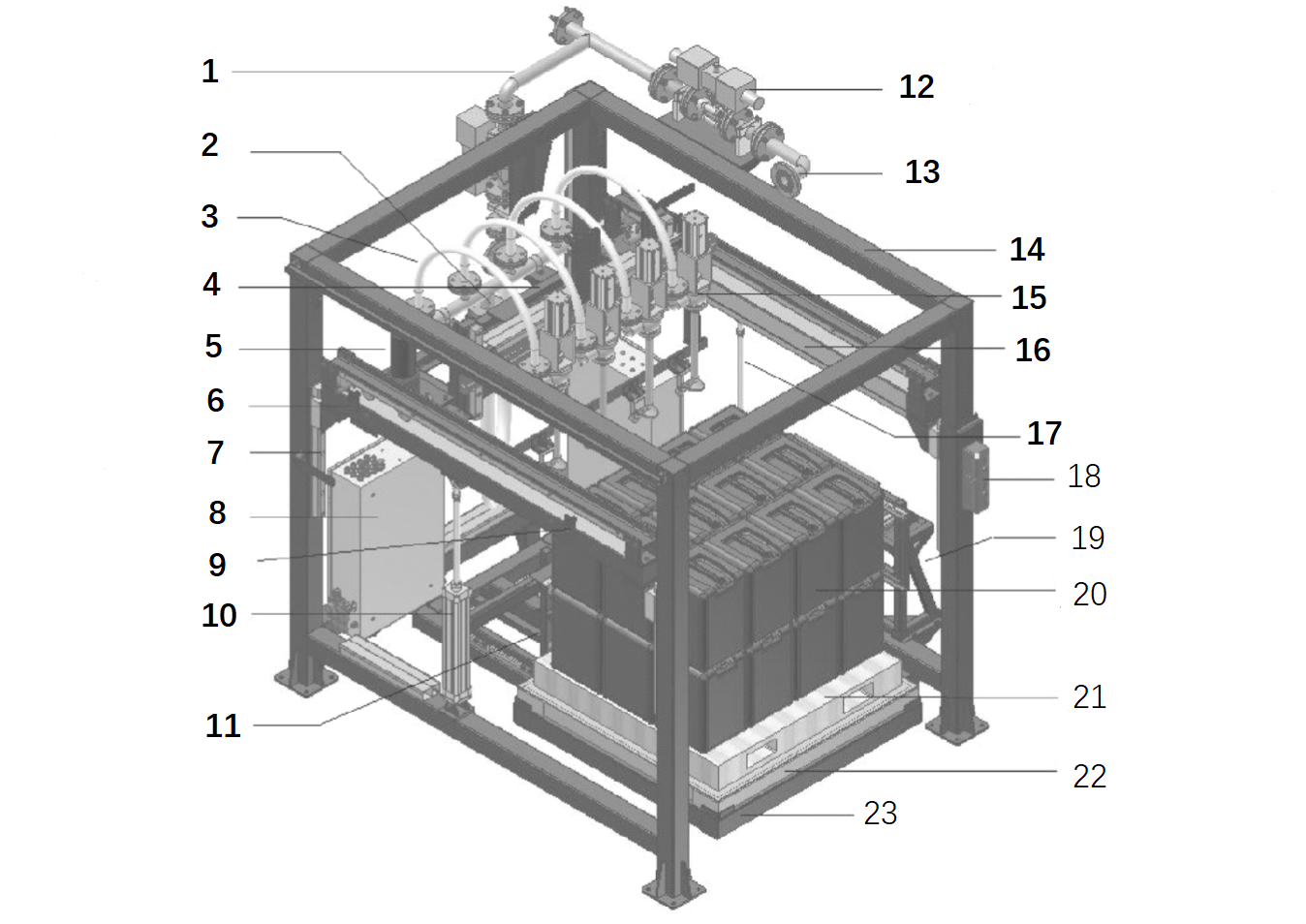
1. Material pipeline 2. Lifting cylinder of filling head 3. Material hose 4. Horizontal moving frame 5. Stepping motor 6. Zero detection switch 7. Lifting linear slide rail 8. Pneumatic control box 9. Limit detection switch 10. Left lifting cylinder 11. Front positioning mechanism 12. 200L and IBC barrel filling ball valve 13.200L and IBC barrel filling head flange interface 14. Steel structure bracket platform 15. Filling head 16. Right guide rail lifting bracket 17. Right lifting cylinder 18. Operation button box 19. Right positioning mechanism 20. Double-layer filling barrel 21. Pallet 22. Scale body 23. Scale body base.
2. Working principle
The working principle of the filling machine is shown in Figure 2. A filling is carried out in two batches. First, the first layer of square barrels (the first layer placed close to the tray) is placed, and then the first batch of filling is completed, that is, the first layer of 12 barrels is filled, and then the second batch of filling is carried out by placing the second layer of square barrels. Each layer has 12 square barrels, which are arranged in three rows and four columns, and are defined as the first row and the second row from back to front. The given starting and stopping of filling machine materials is realized by indirect control of diaphragm pump by PLC, and fast feeding and slow feeding are realized by controlling fast and slow feeding coils of filling valves corresponding to each spray gun.
In the stage of manually placing empty barrels before filling, PLC controls the actions of the front and right positioning cylinders, which can ensure the fixity of the rear and right positions of empty barrels. In this way, when manually placing empty barrels, as long as the empty barrels are attached to the rear and right positioning plates, and all empty barrels are placed tightly, the orientation of barrel openings should be consistent. And the left and right lifting cylinders can lift or lower the whole spray gun assembly. When the assembly is in the lowered position, the first layer of square barrels can be filled, and when the assembly is in the lifted position, the second layer of square barrels can be filled. The PLC control stepping system can realize the accurate positioning of each row of barrels in the front and back directions; Through debugging, the distance between the four-bar spray guns is consistent with the transverse distance of the barrel mouth, thus realizing accurate positioning in the left and right directions. After the automatic mouth searching is completed, PLC controls the spray gun filling valve to carry out fixed value filling barrel by barrel according to the received weighing data.

1. Weighing body 2. Weighing instrument 3. Fixed value filling 4. Spray gun filling valve 5. Filling head lifting cylinder 6. Material setting 7. Diaphragm pump 8.PLC 9. Stepping system 10. Driving rack 11. Horizontal moving frame 12. Spray gun assembly translation and positioning 13. Left and right lifting cylinders 14. Spray gun assembly lifting and positioning 15. Automatic mouth searching 16. Front and right positioning cylinder 17. Manual discharge.
The design scheme of the control system
The design scheme diagram of the filling machines control system is shown in Figure 3. The filling device and other components are explosion-proof, such as stepping motors, a weighing platform, pneumatic solenoid valves, a proximity switch, a switch button box, etc. PLC is the control center in the figure, and the weighing sensor is connected to the weighing instrument through the sensor junction box and intrinsic safety barrier. PLC and the weighing instrument exchange information through serial communication. This type of proximity switch transmits the signal to PLC through an explosion-proof junction box and a transformer isolation safety barrier. PLC controls the stepping driver, which then drives the stepping motor to run, and the stepping motor drives the transmission gear rack. The indicator light is used to indicate the filling status and output the alarm status, and the relay is used to indirectly control the start and stop of the diaphragm pump. Communication connection with the touch screen PLC, used for filling machines debugging, parameter setting, data display, status and alarm output, etc.
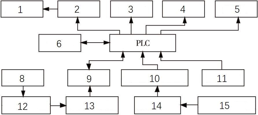
1. stepper motor 2. stepper driver 3. indicator light 4. pneumatic solenoid valve 5. relay 6. touch screen 7. PLC 8. weighing sensor 9. weighing instrument 10. transformer isolation barrier 11. switch button 12. sensor junction box 13. intrinsically safe barrier 14. explosion-proof junction box 15. intrinsically safe proximity switch.
Hardware design of filling machines system
Hardware design of filling machines system, including PLC I/O distribution list, electrical schematic design, component list, etc., only the I/O distribution list and some electrical schematic design are described below.
1. PLC input/output distribution list
The input/output distribution list of PLC of the filling machine control system is shown in Table 1.
Table 1 Distribution List of PLC Input/Output of Filling Machine
| input address | signal | output address | signal |
| I0. 0 | manual | Q0. 0 | pulse output (step) |
| I0. 1 | automatic | Q0. 2 | direction Control (Step) |
| I0. 2 | emergency stop | Q0. 5 | filling in progress |
| I0. 3 | manually move forward with the spray gun | Q0. 6 | alarm |
| I0. 4 | manual backward movement of spray gun | Q0. 7 | diaphragm pump control |
| I0. 5 | start the first step | Q2. 0 | position the first step on the front side |
| I0. 6 | start the second step | Q2. 1 | the front side locates the second step |
| I0. 7 | stop filling | Q2. 2 | right positioning cylinder |
| I1. 0 | first step position | Q2. 3 | right lifting cylinder on the first step |
| I1. 1 | second step position | Q2. 4 | lifting of filling head |
| I1. 2 | keg/vat | Q2. 5 | fast-forward valve of spray gun 1 |
| I2. 0 | left lift to position | Q2. 6 | slow inlet valve of spray gun 1 |
| I2. 1 | lift left to position | Q2. 7 | fast-forward valve of spray gun 2 |
| I2. 2 | step zero | Q3. 0 | spray gun 2 slow feed valve |
| I2. 3 | step Limit | Q3. 1 | left Lifting Cylinder |
| I2. 4 | front side retracts into place | Q3. 2 | 200L slow inlet valve |
| I2. 5 | the right side retracts to the position | Q3. 3 | 200L fast-forward valve |
| I2. 6 | raise right to position | Q3. 4 | 20L filling valve |
| I2. 7 | lift right to the position | Q3. 5 | fast-forward valve of spray gun 3 |
| I3. 0 | spray gun rises to the position | Q3. 6 | spray gun 3 slow inlet valve |
| I3. 1 | spray gun down to position | Q3. 7 | spray gun 4 fast-forward valve |
| I3. 2 | standby | Q4. 0 | spray gun 4 slow inlet valve |
2. Partial schematic design
Siemens S7-200 with high-cost performance is selected as the PLC system, and its model is CPU 224XP-DC/DC/DC. The main module is equipped with two serial communication Ports, Port1 is connected to weighing instruments, and Port0 can be connected to printers. The expansion module is configured with digital expansion modules em223 16dcin/16rly and em223 8dcin/8rly, and a communication module EM2777 is configured to communicate with the touch screen. The electrical wiring schematic diagram of the PLC main module is shown in Figure 4. In the figure,+E1 and-E1 are the positive and negative signals of independent switching power supply DC24 V, and+E2 and-E2 are the positive and negative signals of independent switching power supply DC5 V. The control signal power supply of the stepping controller is required to be DC5 V. In the figure, the 1M and 1L+terminals are respectively connected to the anode and cathode of the switching power supply DC5 V. The power supply terminals L+and M are connected to the positive and negative terminals of DC24 V respectively. Select switches SA11 and SA12 and buttons SB11, SB12 and SB13 are all arranged on the panel of the positive pressure cabinet, and select switches SA21 and SA22. And buttons SB21, SB22 and SB23 are arranged on the explosion-proof operation button box. The wiring schematic diagram of the stepping drive system is shown in Figure 5. The power supply of the stepping driver MC01 is AC 220 V, the power supply terminals are L22 and N22, and PE is the grounding wire. The control signal comes from the output of PLC, and the pulse signal terminals are 0140 and-E2, and the direction signal terminals are 0142 and-E2. The wiring schematic diagram of this type of proximity switch is shown in Figure 6, and SK01 - SK04 are intrinsically safe proximity switches used in explosion-proof fields. It is a two-wire connection mode. Through the transition of the intermediate explosion-proof junction box J-BOX2, the signal lines are connected to the transformer safety barriers SI-02 and SI-03 in the positive voltage control cabinet. L12 and N1 are 220 V AC to supply power to the safety barriers, and 0190 - 0193 are signal lines connected to the input ports of PLC.

Figure 4 Schematic diagram of the electrical wiring of the PLC main module
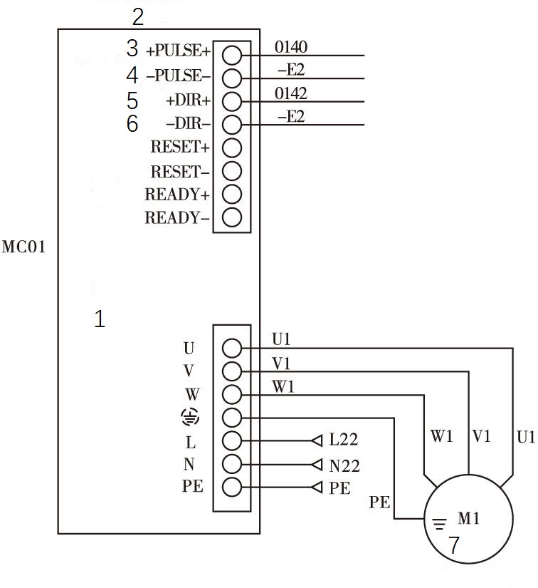
Figure 5 Schematic diagram of stepping drive wiring (1. Stepping motor controller 2. Translation of front and rear blades of spray gun 3. Pulse signal 4. Pulse signal 5. Direction signal 6. Direction signal 7. Stepping motor)
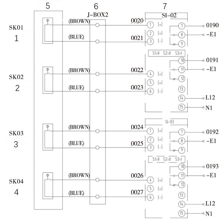
Figure 6 Wiring schematic diagram of intrinsically safe proximity switch (1. Lift left to position 2. Lift left to position 3. Step zero position 4. Step limit position 5. Proximity switch 6. Explosion-proof junction box 7. Transformer isolation safety barrier)
Software design of filling machine system
Software design includes analyzing control requirements, describing control flow and designing a PLC program.
1. Analysis of control requirements
The control requirements of this filling machine are divided into three working modes, namely automatic mode, semi-automatic mode and manual mode.
(1) automatic mode
Automatic mode is the filling mode during normal operation. After manually placing a layer of empty barrels or a layer of empty barrels, the front positioning cylinder and the right positioning cylinder can be controlled to move and position by operating a layer of positioning or layer of positioning selection switch, and then the empty barrels are manually shaped to realize the fixed position placement of the layer of empty barrels or layer of empty barrels; After the empty barrel on the first floor is placed, press the "Start on the first floor" button, the left and right lifting cylinders will automatically descend to the set position, then the stepping system will drive the spray gun device to move forward from zero point to the position just above the opening of the first row of barrels and stop, the spray gun on the filling head will automatically descend, and the four-bar spray gun will be inserted into the four openings respectively, then the first barrel in the first row will be filled at a fixed value, and the second barrel will be filled after the first barrel is filled. Until the four barrels in the first row are filled in sequence, the spray gun of the filling head automatically lifts and extends out of the barrel, and then the stepping system drives the spray gun device to accurately move from the top of the first row of barrel openings to the top of the second row of barrel openings and stop. The filling process of the second row is the same as that of the first row, and the same control requires the filling of the third emptying barrel. After all of the three emptying barrels on the first floor are filled and the spray gun head is detected to be in place, the stepping system drives the spray gun device back to the zero position, and then lifts the air cylinder left and right to lift the spray gun device and detect it. The start-stop control of the diaphragm pump requires that every barrel filled should be started and stopped. The touch screen can set the parameters related to filling. The parameters are divided into two categories: filling product parameters and filling general parameters. The filling product parameters are control parameters related to filling materials, and the filling general parameters are some parameters unrelated to materials.
(2) Semi-automatic mode
Semi-automatic filling mode is an abnormal filling mode, which is generally used when the system can't accurately find the barrel mouth. When filling with a semi-automatic function, it is necessary to manually operate the stepping system to move the spray gun device to align the spray gun with the barrel mouth, and then press the button of "First Floor Start" or "Second Floor Start" to complete the filling of a row of 4 barrels. Compared with the automatic mode, the main difference is that it is necessary to manually operate the stepping system to find the barrel mouth before each filling.
(3) Manual mode
Manual mode is used for equipment debugging or troubleshooting, such as setting the selector switch to the "Manual" position and selecting to enter the "Manual Function" screen on the touch screen to manually operate the cylinder or stepping system.
2. Describe the control process
In the automatic mode, the filling flow chart of the first-floor square barrel is shown in Figure 7. In the initial state, a layer of 12 empty barrels is manually placed on the wooden tray on the scale, and the empty barrels are positioned. Then, a layer of the start button is pressed, and the subsequent actions are automatically completed by the filling machine. The lifting cylinder moves down, and the whole spray gun device moves forward under the stepping drive after it reaches the position and moves to the top of the first row of barrels. The filling spray gun descends, and the gross weight is judged after it reaches the position. In the non-gross-weight state, peeling is carried out. After successful peeling, peeling is carried out. Fill the first row of 2 ~ 4 barrels according to the same process. A similar process completes the filling of the second row and the third empty bucket, then the filling spray gun is lifted, and moves back to the stepping zero point after reaching the position of the spray gun device, and then the lifting cylinder moves up. After reaching the position, the filling process of the first-floor square bucket is all finished.
After the first-layer square barrel is filled, it is necessary to manually cover and screw the cover, and then the second-layer square barrel is filled. In automatic mode, the filling process of the second layer square barrel is basically the same as that of the first layer.
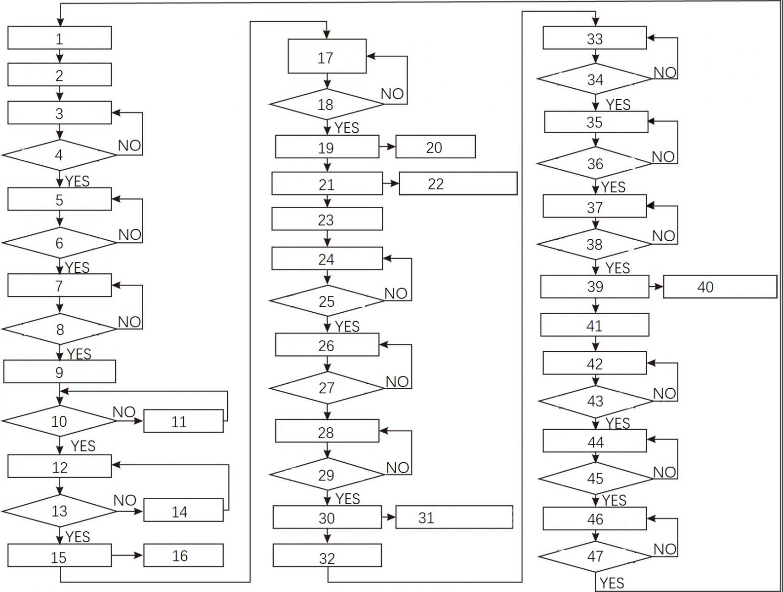
1. Initial state 2. The first floor starts. 3. The lifting action drops. 4. The lifting is in place. 5. The spray gun device moves forward. 6. A row of barrels is in position. 7. The filling spray gun drops. 9. The first barrel in the first row is filled. 10. Gross weight state. 11. The peeling order is issued. 13. Peeling is successful. 14. Peeling is done again. 15. Fast/ Slow filling 16. Turn on the diaphragm pump 17. Compare the filling value with the target value 18. Reach the target value 19. Close the filling valve 20. Turn off the diaphragm pump 21. Fill the first row of 2-4 barrels 22. The process is the same as that of the first barrel 23. Complete the first row of 1-4 barrels 24. Lift the filling spray gun 25. Raise the spray gun to position 26. Move the spray gun device forward 27. Fill the second row of barrels 28. Fill 1-4 barrels in the second row 31. The process is the same as that in the first row 32. Complete 1-4 barrels in the second row 33. Raise the filling spray gun 34. Raise the spray gun in position 35. Advance the spray gun device 36. Position of the third row of barrels 37. Lower the filling spray gun 38. Lower the spray gun to position 39. Fill 1-4 barrels in the third row 40. The process is the same as that in the first row 41. Complete the first row 1-4.
3. Design PLC program
The design of the PLC program is based on control requirements and control flow. It adopts a modular program design structure and is realized by calling subroutines in the main program. The subroutines mainly include data recording, DP communication of upper computer, output control, instrument communication, filling flow, first-floor action, second-floor action, step control, manual function, semi-automatic, touch screen time setting, touch screen alarm and printing functions, etc. Function description of some subprograms. The filling subprogram mainly controls the filling process of each barrel. Its functions include judging the balance on the empty barrel, judging the collision of the spray gun with the barrel, controlling the peeling of the instrument, controlling the fast and slow speed of the filling valve, and judging the out-of-tolerance filling value, etc. Stepping control subroutine, whose functions include judging and controlling the direction of stepping control, calculating the corresponding relationship between the number of stepping pulses and the actual moving distance, calculating and assigning the number of pulses from the stepping zero position to the first row of barrels, calculating and assigning the number of pulses from the first row of barrels to the second row of barrels, planning and setting the moving speed of the stepping system, controlling four PTO (Pulse Train Output) instruction modules in stepping control, etc. The program segment of the PTO 0-RUN module is as follows:
LD SM0. 0
= L60. 0
LD motor_run1: M13. 0
O motor_run2: M13. 1
O motor_run3: M13. 2
O motor_run4: M13. 3
O Manual stepping pulse: V308.1
= L63. 7
LD L60. 0
Call0 _ run: sbr10, l63.7,0, step limit bits: i2.3, v2700.0, VB2701, VB2702, VB2703, VD2704
In the above program, the enable signals of PTO0 _ run instruction are SM0.0, M13.0, M13.1, M13.2, M13.3 and V308.1, which are the conditions for the PTO0-Run instruction module to run, the envelope number of PTO 0 is 0, and the step limit I2.3 is the stop condition of PTO 0.
The 25L square barrel weighing automatic filling machine has been successfully applied in a foreign-funded enterprise. After many times of debugging, the design was optimized according to the actual needs of customers, and the equipment was in good running condition. It is of popularization significance for the application of other square barrel filling machines. In the process of equipment application, some aspects that can be further optimized are also found. For example, the forward and backward movement of the spray gun device is a step-by-step one-side drive, and the deviation of the horizontal displacement between the driving side and the driven side will occur during operation, which will affect the positioning accuracy. Subsequent improvements can consider designing the synchronous drive of both sides of the spray gun device to improve the positioning accuracy and speed.
